Electronics
The Whats and The Hows of Fault Mappers
With cabling in complex communications networks like the NBN reaching colossal lengths, any faults can be both time-consuming and difficult to pinpoint. Testing engineers have several methods of locating breaks and faults in cable, and the fault mapper, or a time-domain reflectometer is an effective straightforward device used precisely for that reason. Defects in cabling can result from a number of reasons. This includes short circuits, splicing, open connections, water ingress and damage to sheathing or connections.
What are Fault Mappers?
A Time Domain Reflectometer (TDR), or more commonly called a fault mapper, is an electronic device used to determine the location and magnitude of cable faults along the length of a conductive cable. It is very effective in long, complicated or inaccessible cabling, like communication lines and circuit boards.
How Do Fault Mappers Work?
Fault Mappers work using a similar principle to radar. They send a low voltage pulse signal into one end of the cable being tested and detect any changes in impedance, or impedance discontinuity. Any changes are reflected back to the testing device. The initial pulse and the reflected signal are timed, and with a set speed (or velocity of propagation –VoP), the location that triggers a reflection can be pinpointed. Results are displayed on the fault mapper screen. Depending on the changes in impedance readings, the fault mapper can also determine the type of fault in the cable. If the fault mapper detects no changes in impedance, then the cable is without fault.
Where are Fault Mappers Used?
Fault mappers or time domain reflectometers are used in a range of fields. The most obvious is for detecting faults in telecommunications cable landlines. Very long telephony and NBN lines can be tested if a malfunction is suspected, and there won’t be the need to dig up the entire length of the line. Using a fault mapper is a quick method in locating cable faults with considerable accuracy. In addition, communications companies also use fault mappers when conducting regular line maintenance. The device can locate changes in impedance levels due to corrosion, impact and degradation of the insulative sheathing of cables. A less obvious use is detecting any fault due to outside tampering. Wiretaps into the lines produce impedance changes and these are easily located with a fault mapper.
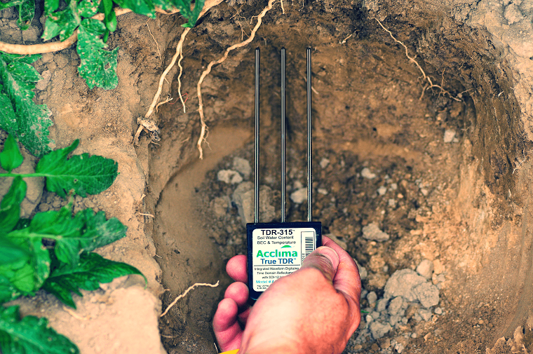
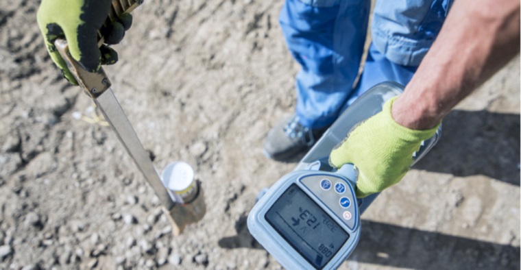
Outside of telecommunications, a fault mapper is used in complicated circuitry like detecting faults in printed circuit boards and for semiconductor devices. Since it works within set parameters, fault mappers are also used to calculate the length of both electrical and communication lines and trace cabling and cable runs in walls, circuits and other surfaces. Similar units using time domain reflectometry are used in agriculture to evaluate soil moisture levels and faults in aircraft wiring. These are able to perform tests in-flight, with safe usage and testing on live wiring.
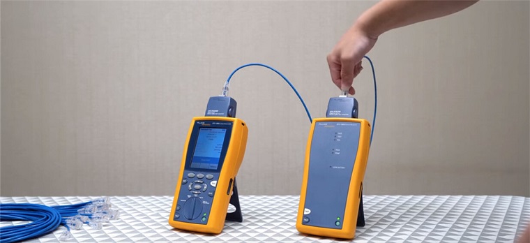
The Unit
Fault Mappers are small lightweight and thus portable devices featuring an LCD screen that displays the findings. Cables are inserted into test lead probes on the top of the device and up and down cursors are used to fine-tune and pinpoint the precise location of possible faults and termination points. All fault mappers have a host of automatic functions, as auto trace and auto find in ensuring that faults are located quickly and easily, without too much input from the tester.
Advanced variants can locate defects in a range of different cable types and extreme lengths. Coaxial, twisted pair and parallel cables up to 20000 metres in length can be tested. Fault mappers have adjustable impedance ratings, working at 25, 50, 75 or 100 Ohms to locate any impedance mismatch in faulty lines. They can detect various faults in the cable like open connections, short circuits, wiretaps, splitters, increased moisture levels, lines with high resistance, damaged insulation, corrosion and more. Built-in tone generators allow testers to trace and locate cable runs in inaccessible locations. For testing optical fibres, an optical time-domain reflectometer or OTDR is used. It works on the same principle as an ordinary fault mapper.
Advantages and Disadvantages of Fault Meters
Fault mappers are small, lightweight and relatively easy to use. Within the scope of other test equipment, a fault mapper also is affordable and versatile, able to trace, locate and distinguish between different faults in a range of different cables and cable lengths. Low test voltage values are used and all units have integrated over-voltage protection (above 250V) to ensure tester safety. Changes in impedance in the cabling is easily identified and found. Units with inbuilt memory or USB ports can be used to store historical data of previous tests to diagnose frequent issues and whether cables need replacing.
Disadvantages include the need for highly-skilled and qualified personnel in interpreting the data on the screen and possible concerns with electrical noise from surrounding cabling or equipment which may interfere with the low-voltage pulse signal. In addition, pulse blind spots are generated in certain conditions and affect overall precision.
Where are Fault Mappers Sold?
Fault mappers are sold by stores stocking a range of industrial, electrical and other testing equipment. Prices vary among brands, and are dependent on the features, testing range and included accessories.